
LIFT COMMUNICATION · EXISTING INTERCOM CONNECTION
Wireless extension
for OTIS intercoms
A one-group extension intended for existing OTIS four-party intercoms, connecting to the duty side through 4G IoT wireless communication. Match the configuration to the existing intercom version, wiring and site conditions.
Match the existing intercom, then the communication setup
Brand and model names identify the intended existing intercoms; confirm the specific site version.
Existing intercom fit
Provide the model label, current wiring and four-party intercom locations for existing OTIS four-party intercoms. Check these against the single terminal group.
Wireless communication
Confirm operator coverage, accounts and console communication. The RJ45 socket alone does not establish additional IP functions.
INTERCOM SYSTEM · CONNECTIONS
From the lift
to the duty station.
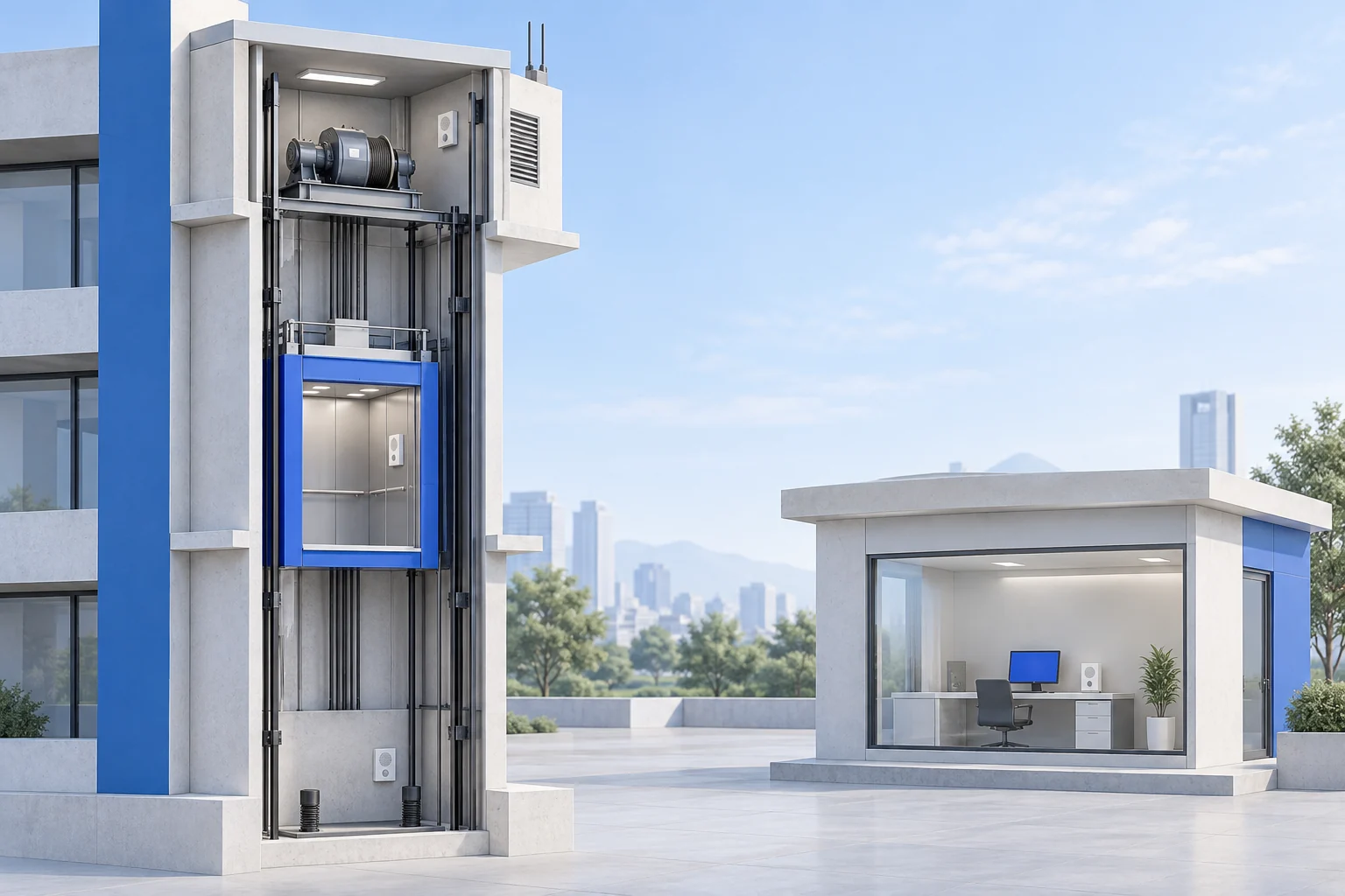
Lift-side intercoms connect to the duty side through a wireless extension and 4G IoT communication. Confirm site coverage, account and console configuration.
- AMachine-room intercom
- BCar-roof intercom
- CCar intercom
- DPit intercom
- 01
Lift-side intercoms
Machine room · car roof · car · pit
- 02
Wireless extension
This model: 1 terminal group
- 03
4G IoT communication
Confirm operator, coverage and account
- 04
Duty station
Select the console for the setup
The four locations are intercom positions; this model has one intercom terminal group. Location count and terminal-group count describe different things. The AI-generated scene is conceptual, not a product image or a terminal or installation wiring drawing.
Three checks before connection
Existing intercom model and wiring system; the terminal group, supply and actual wiring; operator coverage, account and duty-console configuration.
Original wiring references
Chinese-language originals. Open when needed.
CONFIGURATION & PARAMETERS
Panel and selection conditions
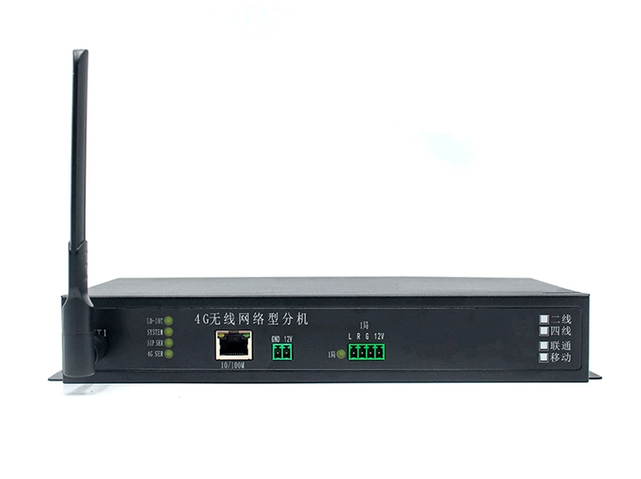
This entry describes a 4G wireless, one-group configuration for existing OTIS four-party intercoms. The photo shows one terminal group and unselected options. Check site coverage, account conditions and the intercom version individually.
- Intended intercoms
- existing OTIS four-party intercoms
- Communication
- 4G IoT wireless communication
- Configuration
- One intercom terminal group (panel: 1局)
- Panel name
- 4G wireless network extension
- Visible network ports
- One RJ45 port, marked 10/100M; confirm configured use
- Intercom terminals
- 1局 (group 1): L, R, G, 12V
- Power check
- Panel: GND, 12V. Text entry: DC12V 2A. Confirm the actual supply.
- Panel options
- 2-wire / 4-wire and Unicom / Mobile: all boxes unselected
Bring the existing intercom and site connection details
Existing intercom model
Provide the model label, version, lift name and original system connections for existing OTIS four-party intercoms.
Terminals and power
Photograph 1局, L/R/G/12V, the wiring-system options and power markings. Confirm actual pin assignments, polarity and version.
Wireless conditions
Record site coverage, operator, account conditions, antenna position and console model. Unselected boxes do not identify an operator.
MODEL & SITE FIT
Confirm the configuration for your OTIS intercoms
Provide model and wiring photos for existing OTIS four-party intercoms, with site coverage, account, console and power details.