
NETWORK EQUIPMENT · BACKUP POWER
Multi-output
UPS
Power network equipment in lift calling systems. Match voltage, current and connectors for media converters, switches and other loads, then confirm the battery configuration and required backup duration.
Prepare backup power around the network loads
The source description names 5V media converters and 9V switches as uses. Match each actual device’s nameplate and connector requirements individually.
Load side
List the network devices that need power, recording voltage, operating current, connector and polarity for each.
Power-supply side
Confirm the supply and battery configuration against total load, installation conditions and backup requirements, including output-current allocation.
NETWORK EQUIPMENT · POWER
Backup power,
built around network loads.
Start with the load list for media converters, switches and other network equipment. Match voltage, connector and current requirements for each device.
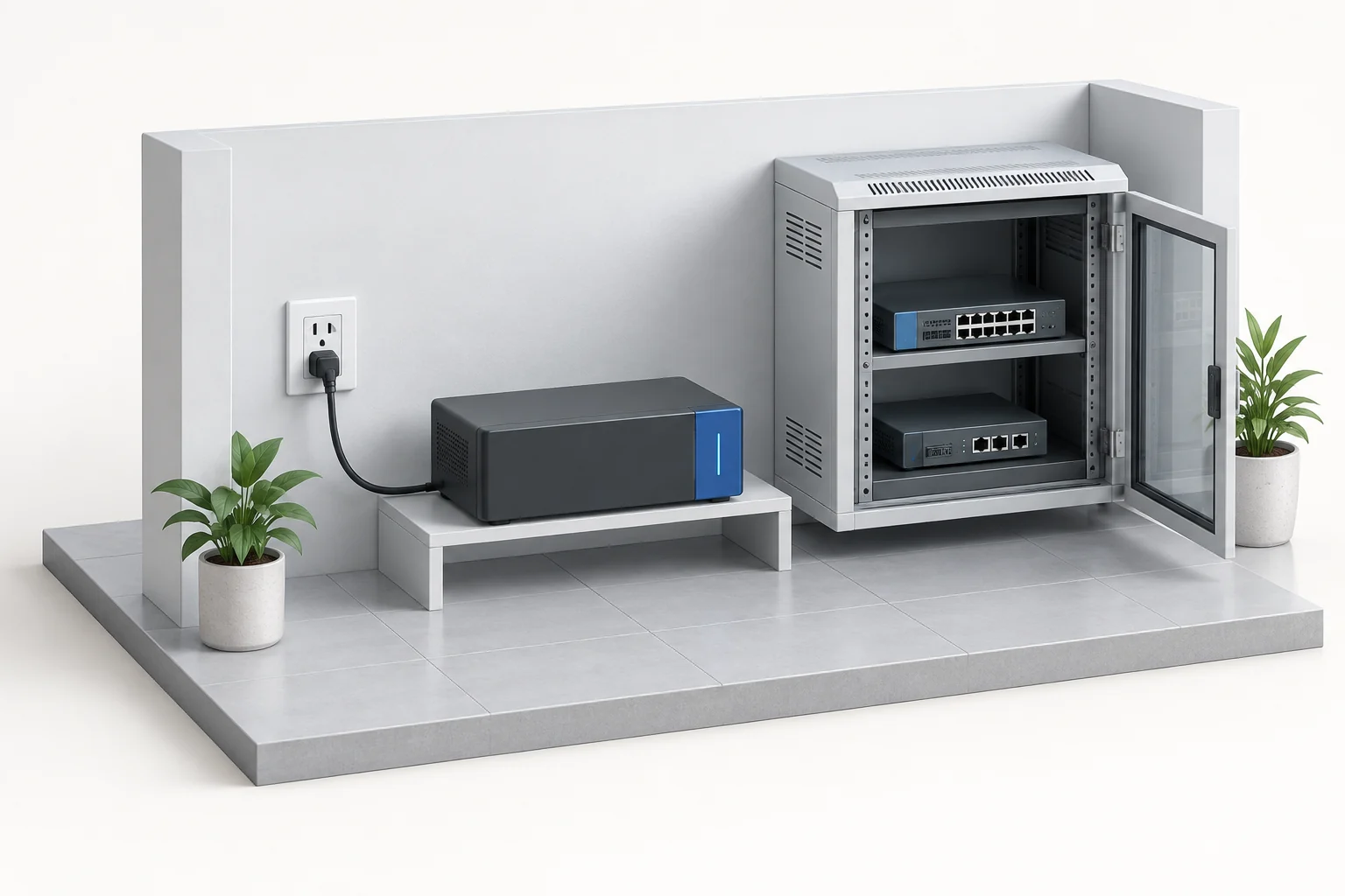
- AInput supply
- BBackup supply
- CNetwork equipment
- 01
Input conditions
Site power and installation space
- 02
UPS backup supply
Loads, battery and output allocation
- 03
Network equipment loads
Check voltage, current and connectors
Illustrates system roles. Use the product photos and original references on this page for equipment appearance, interfaces and configuration.
Size backup duration from actual loads
Check operating currents and simultaneous use, then confirm the battery configuration and backup duration. Capacity options on the original panel do not identify the fitted choice.
Original dimensions
Chinese-language originals. Open when needed.
The image marks 20cm, 12cm and 4cm and retains the original battery options. Confirm the fitted configuration, connectors and installation space.
CONFIGURATION & PARAMETERS
Read the panel and dimension drawing
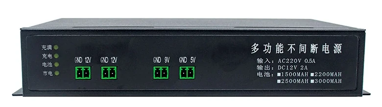
The panel lists multiple battery-capacity options without identifying the fitted choice for this entry. Confirm battery capacity and backup duration when specifying the configuration.
- Input marking
- AC 220V, 0.5A
- Output marking
- DC 12V, 2A; not a per-port current allocation
- Output terminals
- Two 12V groups, one 9V and one 5V, each with GND
- Dimensions marked in the image
- 20cm wide × 12cm deep × 4cm high
- Rear panel
- Power input socket and switch
Start by listing the equipment to power
Voltage and connectors
Record input voltage, connector and polarity for each device; match 5V, 9V and 12V requirements.
Load and battery
Provide operating currents, simultaneous-use conditions and required backup duration. Confirm total load and battery configuration.
Installation and maintenance
Provide space, input-power conditions and maintenance arrangements. Check dimensions, cabling and replacement access.
MODEL & SITE FIT
Use the load list to select the power configuration
Bring nameplate and connector photos for each load, operating currents, required backup duration and installation-space details.