
LIFT COMMUNICATION · DUTY CENTRE
IP video
console
Connect to lift-side equipment over the project IP network and receive calls with video at the duty centre. The console has a 7-inch capacitive touchscreen and supports recording, audio/video linkage and hands-free calling.
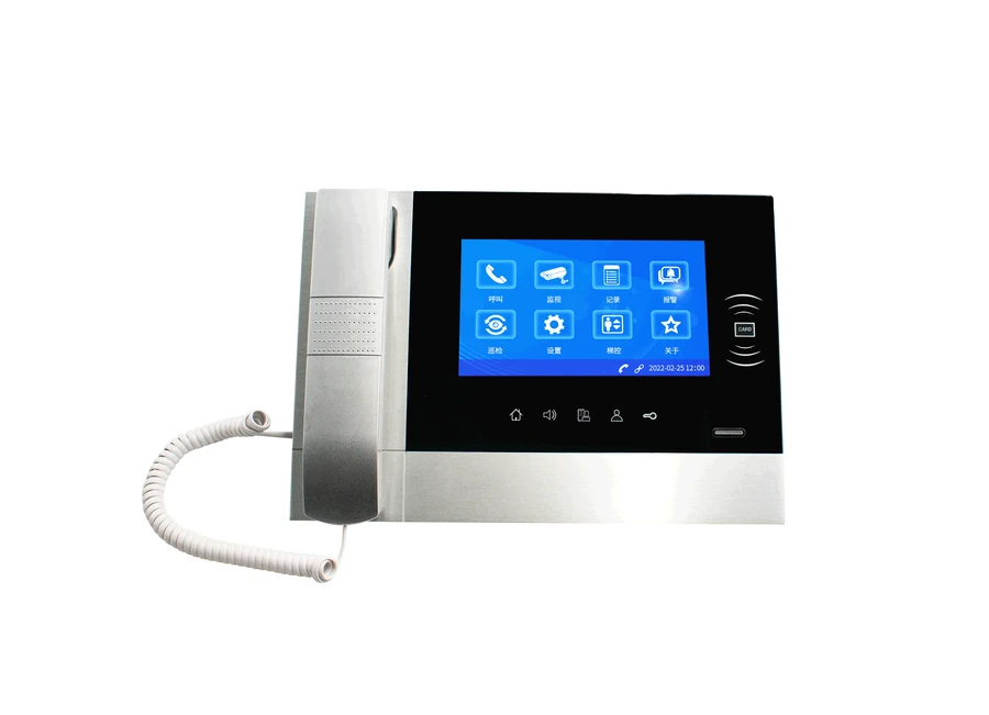
Organise calling and video on the project network
Consoles, network extensions and cameras have separate access conditions. Identify call endpoints, then video sources and viewing permissions.
Duty-side viewing
Receive calls and view through the touchscreen. Define which lifts need video linkage and recording.
Field integration
Check extensions, cameras and network paths. A video console does not establish direct compatibility with every camera.
DUTY CENTRE · RECEIVING
A clear receiving point
at the duty centre.
Lift-side intercoms and extensions reach the duty side over the project IP network. Define staff and receiving points, then check access paths and addressing.

- ALift site
- BDuty receiving point
- 01
Lift side
Intercoms and matching extension
- 02
Project IP network
Access paths and addressing
- 03
Duty console
Video · receive calls and view video
Illustrates system roles. Use the product photos and original references on this page for equipment appearance, interfaces and configuration.
Video needs a matched source
Car camera / video source → access method and network path → video console. Provide camera models and the lift list, then confirm viewing permissions, recording and linkage configuration.
Original supporting references
Chinese-language originals. Open when needed.
Video consoles appear at the lower right; non-video models are above. This calling diagram is not a camera compatibility list.
This image explains a single-port extension and intercom wiring. Other equipment appears in the lower two-party drawing; it does not establish built-in 4G or those interfaces on the console.
CONFIGURATION & PARAMETERS
Console functions and configuration
Display and calling functions come from this model’s description. The source also says “wireless” but lists Ethernet/Internet networking; confirm the actual version rather than infer built-in 4G.
- Networking parameters
- IP; Ethernet/Internet
- Display
- 7-inch capacitive touchscreen
- Calling and records
- Hands-free calls, recording and audio/video linkage
- Video equipment
- Car-camera linkage; confirm the access method
- Protocol and voice
- SIP; G.711/722
- Power
- DC 12V, 2A
Match the console to site conditions
Calling configuration
Provide extension/intercom models and lift names to define console communication.
Video and permissions
Provide camera models, access methods, viewing roles and recording requirements.
Project network
Confirm access points, addressing and maintenance conditions for the actual networking version.
MODEL & SITE FIT
Match each calling endpoint with its video source
Bring the console access point, extension list, camera details and viewing/recording requirements.